ISO 26262 Part 5 Explained – Product Development at the Hardware Level
Modern vehicles rely on highly complex electronic hardware to perform safety-critical functions such as braking, steering, battery management, and advanced driver assistance.
To ensure that these systems remain safe even in the presence of hardware failures, automotive engineers must follow a structured hardware development process.
This is the purpose of ISO 26262 Part 5 – Product Development at the Hardware Level.
Part 5 defines how Hardware Safety Requirements are implemented, how hardware architectures are evaluated, and how random hardware failures are analyzed and mitigated throughout development.
In this article, we explain the structure of ISO 26262 Part 5 and its key activities.
If you want to deepen your understanding of ISO 26262, ASPICE, Automotive Cybersecurity, and other engineering standards for safety-critical systems, explore our complete online training portfolio:
Unlike software, hardware is subject to physical degradation and random failures.
Semiconductor aging, manufacturing defects, electromagnetic interference, and environmental influences can all affect the reliability of electronic components.
Without systematic hardware safety engineering, organizations may face:
undetected hardware faults
insufficient fault tolerance
inadequate diagnostic coverage
increased risk of hazardous failures
reduced product reliability
ISO 26262 Part 5 provides a structured framework for designing hardware that can detect, tolerate, or safely respond to failures before they result in hazardous vehicle behavior.
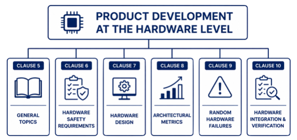
Structure of ISO 26262 Part 5
ISO 26262 Part 5 defines how Functional Safety is implemented throughout the complete automotive hardware development process.
Clause 5 – General Topics
Clause 5 establishes the general principles for Product Development at the Hardware Level.
It provides the framework that guides hardware engineering throughout the project.
Typical activities include:
planning hardware development
maintaining traceability
managing interfaces
coordinating hardware safety activities
supporting communication with system and software engineering
These activities ensure that hardware development remains aligned with the overall Functional Safety objectives established during the earlier phases of ISO 26262.
The core of Part 5 is the transformation of Technical Safety Requirements into a safe hardware implementation.
Typical activities include:
deriving Hardware Safety Requirements
developing the hardware architecture
selecting electronic components
implementing safety mechanisms
allocating safety requirements to hardware elements
documenting hardware design decisions
Typical hardware safety mechanisms include:
watchdog circuits
redundant processing paths
voltage monitoring
clock monitoring
error detection and correction (ECC)
diagnostic circuits
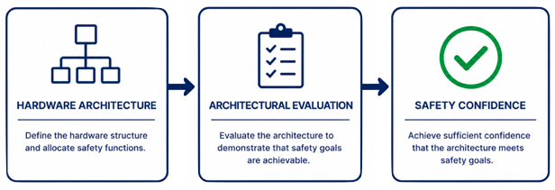
The objective is to create a hardware architecture capable of detecting or controlling failures before they can compromise Functional Safety.
Clause 8 – Evaluation of the Hardware Architectural Metrics
Once the hardware architecture has been defined, ISO 26262 requires its evaluation using quantitative safety metrics.
The three most important Hardware Architectural Metrics are:
Single Point Fault Metric (SPFM)
Latent Fault Metric (LFM)
Probabilistic Metric for Random Hardware Failures (PMHF)
These metrics evaluate different aspects of hardware robustness.
For example:
SPFM measures protection against single-point faults.
LFM evaluates the handling of latent faults that may remain undetected.
PMHF estimates the probability that random hardware failures could violate a Safety Goal.
Together, these metrics provide objective evidence that the hardware architecture satisfies the required level of Functional Safety.
SPFM, LFM, and PMHF provide quantitative evidence that the hardware architecture satisfies the required Functional Safety objectives.
Clause 9 – Evaluation of Safety Goal Violations due to Random Hardware Failures
Hardware components can fail unpredictably during vehicle operation.
Clause 9 evaluates whether these random failures could result in violations of the defined Safety Goals.
Typical activities include:
failure mode analysis
fault propagation analysis
probabilistic evaluation
diagnostic coverage assessment
evaluation of residual risk
Methods such as FMEDA (Failure Modes, Effects and Diagnostic Analysis) are commonly used to support this evaluation.
The goal is to demonstrate that the residual hardware risk remains within the limits required by the assigned ASIL.
Clause 10 – Hardware Integration and Verification
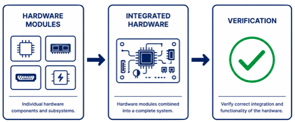
The final stage of Part 5 focuses on integrating the hardware and verifying that it fulfills all allocated safety requirements.
Typical activities include:
hardware integration
interface verification
hardware testing
verification of Hardware Safety Requirements
verification of implemented safety mechanisms
Verification confirms that the hardware has been implemented correctly and behaves as intended under both normal and fault conditions.
Successful verification provides confidence before the project proceeds to higher-level system validation activities.
Hardware Integration and Verification confirm that the implemented hardware architecture fulfills all allocated Hardware Safety Requirements before system validation.
How Part 5 Fits into ISO 26262
ISO 26262 follows a structured development lifecycle in which each part builds upon the previous one.
The relationship can be summarized as follows:
Part 3 establishes the Concept Phase, including HARA, ASIL determination, Safety Goals, and the Functional Safety Concept.
Part 4 develops the Technical Safety Concept and system architecture.
Part 5 implements these requirements within the hardware architecture and evaluates hardware robustness.
Part 6 applies the allocated requirements to software development.
Part 5 therefore serves as the bridge between system-level safety engineering and detailed electronic hardware implementation.
Summary
ISO 26262 Part 5 defines how Functional Safety is implemented during Product Development at the Hardware Level.
Its key activities include:
General Topics
Hardware Safety Requirements
Hardware Design
Evaluation of Hardware Architectural Metrics
Evaluation of Random Hardware Failures
Hardware Integration and Verification
Together, these activities ensure that automotive electronic hardware is designed, analyzed, and verified to achieve the required level of Functional Safety.
For Functional Safety Engineers, Hardware Engineers, Systems Engineers, Electronics Architects, and semiconductor developers, understanding Part 5 is essential for developing safe and reliable automotive electronics.
If you prefer a visual explanation, this video explains ISO 26262-5 Product development at the hardware level step by step: