ISO 13849 Explained – Functional Safety of Machinery
Modern machinery relies heavily on electrical, electronic, pneumatic, hydraulic, and programmable control systems. These systems improve productivity and automation, but they also introduce risks when failures can lead to hazardous machine behavior.
A robot that fails to stop when an operator enters its workspace, a press that unexpectedly starts during maintenance, or a safety guard that is not correctly monitored can all result in serious hazards.
This is where ISO 13849 becomes essential.
ISO 13849 – Safety of Machinery provides a systematic framework for designing and evaluating safety-related parts of control systems. It helps engineers translate machinery hazards into specific Safety Functions, determine the required Performance Level (PLr), design an appropriate safety architecture, and verify that the required risk reduction has actually been achieved.
In this article, we explain the fundamentals of ISO 13849, including Performance Levels, Categories, MTTFd, Diagnostic Coverage, Common Cause Failures, Verification, Validation, and SISTEMA.
Want to develop a deeper understanding of ISO 13849, Performance Levels, Safety Functions, Categories, MTTFd, DCavg, CCF, verification, and validation?
Explore our professional engineering online training covering machinery safety, Functional Safety, and safety-critical systems.
Why Machine Functional Safety Matters
Modern industrial machines contain numerous automated movements and energy sources that can potentially harm operators.
Examples include:
- industrial robots
- automated production lines
- presses
- packaging machines
- conveyor systems
- CNC machines
- automated material handling systems
Traditional mechanical protection alone is often insufficient.
Modern machinery therefore uses safety-related control functions to detect hazardous situations and bring the machine into an appropriate safe state.
Typical protective devices include:
- Emergency Stop devices
- Safety Light Curtains
- Interlocking Guards
- Safety Controllers
- Safety PLCs
- Position Monitoring
- Speed Monitoring
- Safe Torque Off functions
The challenge is not simply implementing these components.
Engineers must demonstrate that the complete Safety Function provides sufficient risk reduction for the specific hazard.
ISO 13849 provides the engineering framework for doing exactly that.
Where ISO 13849 Fits into Machinery Safety
ISO 13849 does not operate in isolation.
Machinery safety normally involves several complementary standards covering different aspects of risk assessment, protective measures, and Functional Safety.
One of the most important starting points is ISO 12100, which provides general principles for machinery risk assessment and risk reduction.
The basic relationship can be simplified as:
Hazard Identification → Risk Assessment → Risk Reduction → Safety Function → Safety-Related Control System
ISO 12100 provides the overall risk assessment and risk reduction framework.
When risk reduction requires a safety-related control function, ISO 13849-1 can be used to design and evaluate the corresponding safety-related parts of control systems.
Another important Functional Safety standard for machinery is IEC 62061.
Additional machinery standards address topics such as guards, interlocking devices, safety distances, and positioning of protective equipment.
ISO 13849 therefore represents an important part of a broader machinery safety framework rather than a standalone solution for every machine safety problem.
From Hazard to Safety Function
One of the most important concepts in ISO 13849 is the transition from an identified hazard to a clearly defined Safety Function.
Consider an industrial robot operating inside a safeguarded cell.
An operator entering the robot workspace while the robot is moving could be exposed to hazardous mechanical movement.
The risk assessment identifies this hazardous situation and determines that additional risk reduction is required.
A Safety Function can then be defined, for example:
When the safety light curtain is interrupted, hazardous robot movement shall be stopped.
This Safety Function can be implemented through a chain consisting of:
Safety Light Curtain → Safety Controller → Robot Drive / Safe Stop
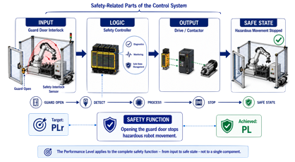
The important point is that ISO 13849 evaluates the complete safety-related control function, not merely an individual safety component.
The sensor, logic, and output elements all contribute to the achieved Performance Level.
Performance Levels in ISO 13849
A central concept of ISO 13849 is the Performance Level (PL).
Performance Levels represent the capability of safety-related parts of control systems to perform a Safety Function under foreseeable conditions.
ISO 13849 defines five Performance Levels:
- PL a
- PL b
- PL c
- PL d
- PL e
The scale progresses from PL a, representing the lowest risk reduction capability, to PL e, representing the highest.
During risk assessment, engineers determine the required Performance Level, commonly abbreviated as PLr.
The safety-related control system must subsequently be designed so that its achieved Performance Level is at least sufficient for the required Performance Level.
Conceptually:
Risk Assessment → PLr → Safety System Design → Achieved PL → Verification
This creates a direct connection between the identified machinery risk and the reliability requirements placed on the Safety Function.
Categories B, 1, 2, 3 and 4
Performance Level is not determined by component reliability alone.
The architecture of the safety-related control system also plays an important role.
ISO 13849 uses five Categories:
Category B
Provides the basic principles for the design of safety-related control systems.
Category 1
Builds upon Category B while using well-tried components and safety principles.
Category 2
Introduces periodic testing of the Safety Function.
Category 3
Uses redundant structures so that a single fault does not normally result in loss of the Safety Function.
Category 4
Provides a highly fault-tolerant architecture with extensive fault detection.
The progression from Category B toward Category 4 generally introduces increasingly sophisticated fault tolerance and diagnostic concepts.
However, Category alone does not determine the Performance Level.
Several additional parameters must be considered.
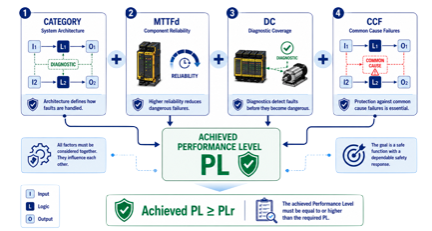
What Determines the Achieved Performance Level?
The achieved Performance Level depends on a combination of architectural and reliability characteristics.
Important parameters include:
Category
The Category defines the fundamental architecture and fault behavior of the safety-related control system.
MTTFd – Mean Time to Dangerous Failure
MTTFd describes the expected reliability of components with respect to dangerous failures.
Higher MTTFd values generally contribute to a higher achievable Performance Level.
DCavg – Average Diagnostic Coverage
DCavg describes the effectiveness of diagnostics in detecting dangerous failures.
Diagnostic measures may include:
- cross-monitoring
- plausibility checks
- feedback monitoring
- test pulses
- redundant signal comparison
CCF – Common Cause Failures
Redundant architectures only provide effective protection when both channels are sufficiently independent.
A Common Cause Failure (CCF) can affect multiple channels simultaneously and therefore undermine redundancy.
Potential causes include:
- shared power supplies
- environmental influences
- electromagnetic interference
- temperature
- contamination
- common design weaknesses
The achieved Performance Level therefore results from the interaction between Category, MTTFd, DCavg, CCF, and other relevant design considerations.
This is why simply selecting components marked with a particular PL does not automatically demonstrate that the complete Safety Function achieves that Performance Level.
ISO 13849 Example: Safety Light Curtain and Robot Cell
Consider a robot cell where an operator could enter the hazardous area.
A safety light curtain monitors access to the robot workspace.
The Safety Function can be expressed as:
If the light curtain is interrupted, hazardous robot movement must stop.
The safety-related control chain consists of three fundamental elements:
Input
The Safety Light Curtain detects access to the hazardous area.
Logic
The Safety Controller processes the safety signal and determines whether the machine must transition to a safe state.
Output
The robot drive executes the required safe stop or removes hazardous drive torque.
The complete Safety Function can therefore be represented as:
Safety Light Curtain → Safety Controller → Safe Robot Stop
Each part of this chain contributes to the achieved Performance Level.
Engineers must evaluate the architecture, component reliability, diagnostic capabilities, and possible common cause failures before demonstrating that the required PLr has been achieved.
This end-to-end perspective is one of the most important practical principles when applying ISO 13849.
Verification, Validation and SISTEMA
Designing the Safety Function is not the end of the process.
Engineers must demonstrate that the design satisfies the specified safety requirements.
Two concepts are particularly important: Verification and Validation.
Verification
Verification asks whether the safety-related control system has been designed correctly according to the specified requirements.
This includes evaluating whether the achieved Performance Level satisfies the required Performance Level:
Achieved PL ≥ PLr
Calculations and architectural evaluations form an important part of this activity.
Validation
Validation goes beyond calculation.
It confirms that the implemented Safety Function actually performs as intended in the real machine and under the relevant operating conditions.
This can involve:
- functional testing
- fault testing
- review of safety-related behavior
- checking interfaces
- confirming the intended safe state
Both activities are necessary. A mathematically adequate architecture alone does not prove that the implemented machine behaves safely.
What Is SISTEMA?
SISTEMA is a software tool provided by the German Institute for Occupational Safety and Health (IFA) to support the evaluation of safety-related control systems according to ISO 13849.
Engineers can model the structure of a Safety Function and evaluate parameters such as:
- Category
- MTTFd
- DCavg
- CCF
- resulting Performance Level
SISTEMA can significantly simplify calculations and documentation, especially for more complex Safety Functions.
However, the tool does not replace engineering judgment.
Engineers must still correctly define the Safety Function, select appropriate architectures, enter valid component data, evaluate dependencies, and validate the final implementation.
SISTEMA supports the engineering process—it does not make the safety decision.
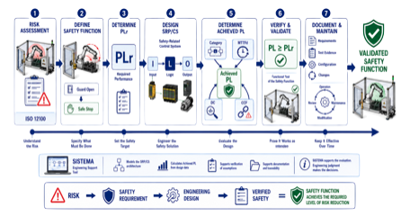
The ISO 13849 Workflow
The overall ISO 13849 process can be summarized as a structured engineering workflow.
1. Identify Hazards
Determine which machine situations could result in harm.
2. Assess Risk
Evaluate the severity and probability associated with each hazardous situation.
3. Define Safety Functions
Determine which control functions are required to reduce the identified risks.
4. Determine the Required Performance Level (PLr)
Establish the necessary risk reduction capability for each Safety Function.
5. Design the Safety-Related Control System
Select an appropriate architecture and suitable safety-related components.
6. Evaluate the Achieved Performance Level
Consider:
- Category
- MTTFd
- DCavg
- CCF
- architectural characteristics
7. Verify the Design
Demonstrate that the achieved Performance Level satisfies the required Performance Level.
8. Validate the Safety Function
Confirm that the implemented function actually provides the intended risk reduction on the machine.
The resulting lifecycle can therefore be summarized as:
Hazard → Risk Assessment → Safety Function → PLr → Design → Achieved PL → Verification → Validation
This workflow connects machinery risk assessment directly with the engineering and validation of the safety-related control system.
ISO 13849 vs ISO 12100 vs IEC 62061
These standards are closely related, but they serve different purposes.
ISO 12100 provides the general methodology for machinery risk assessment and risk reduction.
ISO 13849 focuses on safety-related parts of control systems and uses concepts such as Performance Levels, Categories, MTTFd, DCavg, and CCF.
IEC 62061 also addresses Functional Safety of machinery control systems but uses a different framework based on Safety Integrity Levels and related reliability concepts.
In practical machinery projects, these standards often form part of a larger standards landscape rather than being applied completely independently.
Understanding their respective roles helps engineers select an appropriate approach for each machine and Safety Function.
Key Takeaways
ISO 13849 is one of the most important standards for Functional Safety of machinery.
Its core principles can be summarized as follows:
- Risk assessment establishes the need for risk reduction.
- Hazards are translated into clearly defined Safety Functions.
- Each Safety Function receives a required Performance Level (PLr).
- Performance Levels range from PL a to PL e.
- Categories B, 1, 2, 3 and 4 describe architectural characteristics.
- MTTFd represents reliability with respect to dangerous failures.
- DCavg evaluates diagnostic effectiveness.
- CCF addresses failures that may simultaneously affect redundant channels.
- The complete Safety Function must achieve the required Performance Level.
- Verification confirms that the design meets its requirements.
- Validation confirms that the implemented Safety Function works correctly on the machine.
- SISTEMA can support calculations and documentation but does not replace engineering judgment.
For Functional Safety Engineers, Machinery Safety Engineers, Automation Engineers, Controls Engineers, Machine Designers, and System Integrators, understanding these concepts provides a strong foundation for applying ISO 13849 in real machinery projects.