ISO 13849 Performance Levels Explained – PL a to PL e and PLr
Functional safety in machinery is not simply about adding safety components. A safety-related control function must provide a level of risk reduction appropriate to the hazard it is intended to control.
This is where Performance Levels become important.
ISO 13849 uses Performance Levels from PL a to PL e to describe the ability of safety-related parts of control systems to perform a safety function under foreseeable conditions. Before designing the safety-related control system, the required Performance Level — PLr — must first be determined.
In this article, we explain what Performance Levels mean, how PLr is determined, which factors influence the achieved Performance Level, and how the complete process fits into machinery functional safety.
What Is a Performance Level in ISO 13849?
A Performance Level, commonly abbreviated as PL, describes the ability of safety-related parts of a control system to perform a safety function under foreseeable conditions.
ISO 13849 defines five Performance Levels:
PL a, PL b, PL c, PL d and PL e.
The levels represent increasing capability to reduce the risk associated with dangerous failures. PL a represents the lowest level within this classification, while PL e represents the highest.
However, the Performance Level is not simply selected by an engineer based on how “safe” a machine should be.
The process starts earlier.
Hazards associated with the machine must first be identified and the associated risks evaluated. Where risk reduction depends on a safety-related control function, the required level of risk reduction for that function must be established.
This results in the required Performance Level, or PLr.
The safety-related control system is then designed and evaluated to determine its achieved Performance Level.
A simplified relationship is therefore:
Risk Assessment → Safety Function → PLr → Design → Achieved PL → Verification
This distinction between the required and the achieved Performance Level is fundamental to understanding ISO 13849.
The Five Performance Levels: PL a to PL e
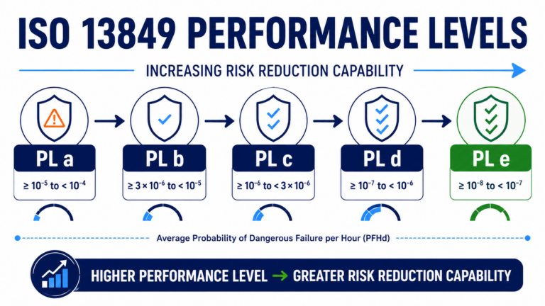
ISO 13849 defines five discrete Performance Levels.
The progression from PL a to PL e corresponds to a decreasing average probability of dangerous failure per hour and therefore an increasing capability of the safety-related control system to provide risk reduction.
| Performance Level | Average Probability of Dangerous Failure per Hour (PFHd) | Relative Capability |
|---|---|---|
| PL a | ≥ 10⁻⁵ to < 10⁻⁴ | Lowest |
| PL b | ≥ 3 × 10⁻⁶ to < 10⁻⁵ | Low |
| PL c | ≥ 10⁻⁶ to < 3 × 10⁻⁶ | Medium |
| PL d | ≥ 10⁻⁷ to < 10⁻⁶ | High |
| PL e | ≥ 10⁻⁸ to < 10⁻⁷ | Highest |
The numerical ranges are important, but they are only part of the concept. Achieving a particular Performance Level requires more than calculating a probability of failure.
Architecture, component reliability, diagnostic capability, resistance to common cause failures and systematic measures all contribute to the final result.
Performance Level a – PL a
PL a represents the lowest Performance Level defined by ISO 13849.
It is associated with safety functions requiring comparatively limited risk reduction. The requirements placed on the architecture and reliability of the safety-related control system are correspondingly lower than for the higher Performance Levels.
That does not mean PL a can simply be selected for a low-risk machine. The required level must result from the risk assessment and the definition of the specific safety function.
Performance Level b – PL b
PL b provides a greater capability for risk reduction than PL a.
As the required Performance Level increases, greater attention must be paid to the reliability and behavior of the safety-related parts of the control system.
The appropriate design therefore depends not only on individual components but on the complete safety-related architecture.
Performance Level c – PL c
PL c represents an intermediate level within the five Performance Levels.
At this point, aspects such as diagnostics and system architecture become increasingly important for achieving the required reliability of the safety function.
A designer therefore needs to consider how dangerous failures can occur and how the control system responds when faults are present.
Performance Level d – PL d
PL d represents a high level of risk-reduction capability and is frequently associated with safety functions for which dangerous failures must be controlled with a high degree of reliability.
Architectural measures, diagnostics and component reliability play an important role.
Redundancy may also become relevant, but redundancy alone does not automatically result in PL d. The complete combination of architectural category, MTTFd, diagnostic coverage, common cause failure measures and other requirements must be considered.
Performance Level e – PL e
PL e is the highest Performance Level defined by ISO 13849.
It corresponds to the lowest range of average probability of dangerous failure per hour within the Performance Level classification.
Achieving PL e places demanding requirements on the design of the safety-related control system. High reliability, suitable architecture, effective diagnostics and appropriate measures against common cause and systematic failures are essential.
Again, the objective is not to achieve the highest possible PL for every safety function. The objective is to achieve a Performance Level that satisfies the required Performance Level derived from the risk assessment.
What Is the Required Performance Level (PLr)?
One of the most important distinctions in ISO 13849 is the difference between PL and PLr.
The required Performance Level (PLr) represents the level of risk reduction required from a particular safety function.
The achieved Performance Level (PL) represents the capability of the implemented safety-related control system.
In simplified terms:
PLr = What is required
PL = What the implemented design achieves
For example, imagine that the risk assessment results in a required Performance Level of PL d for a machine safety function.
The control system must subsequently be designed and evaluated.
If the design achieves only PL c, the requirement has not been met.
If the design achieves PL d, the requirement is satisfied.
This requirement-driven approach prevents engineers from selecting an architecture first and only afterwards attempting to justify its safety performance.
Instead, the necessary risk reduction drives the safety-related design.
How Is PLr Determined in ISO 13849?
ISO 13849 provides a risk graph that can be used to support the determination of the required Performance Level.
The approach considers three fundamental parameters:
S – Severity of injury
F – Frequency and/or exposure to the hazard
P – Possibility of avoiding the hazard or limiting harm
These parameters lead through the risk graph toward a required Performance Level.
The method should not be treated as a purely mechanical calculation. Appropriate engineering judgment and knowledge of the machine, its intended use and foreseeable operating conditions remain important.
This process also connects ISO 13849 closely with ISO 12100, which provides fundamental principles for machinery risk assessment and risk reduction.
Internal link: Mark “ISO 12100” → link to our existing ISO 12100 Explained article.
Severity of Injury – S
The first parameter considers the potential severity of injury.
The risk graph distinguishes between:
S1 – slight, normally reversible injury
and
S2 – serious, normally irreversible injury, including death
The classification should reflect the potential consequences associated with the hazardous situation.
Frequency and/or Exposure – F
The next parameter considers how frequently and for how long people may be exposed to the hazard.
The risk graph distinguishes between:
F1 – seldom-to-less-often and/or short exposure
and
F2 – frequent-to-continuous and/or long exposure
A hazard that is encountered continuously during normal operation can therefore require a different level of risk reduction from one encountered only under limited circumstances.
Possibility of Avoiding the Hazard – P
Finally, the possibility of avoiding the hazardous situation or limiting the resulting harm is considered.
The distinction is between:
P1 – possible under specific conditions
and
P2 – scarcely possible
Relevant considerations can include the speed at which the hazardous event develops, whether the operator can recognize the hazard and whether sufficient time exists to react.
The combination of S, F and P ultimately leads to the required Performance Level.
PLr vs Achieved Performance Level
Determining PLr does not demonstrate that the machine is safe.
It establishes a requirement for the safety function.
The safety-related control system must then be designed and evaluated to determine the Performance Level it actually achieves.
A simple comparison illustrates the principle:
| Required PLr | Achieved PL | Result |
|---|---|---|
| PL d | PL c | Requirement not met |
| PL d | PL d | Requirement met |
| PL d | PL e | Requirement met |
This distinction is especially important during development reviews.
A risk assessment may correctly identify PL d as the required Performance Level, but the implemented architecture could still fail to achieve it.
Conversely, designing every safety function to PL e is generally not the objective either. Safety engineering should provide the necessary risk reduction based on the identified hazards and associated risks.
What Determines the Achieved Performance Level?
The achieved Performance Level does not depend on a single parameter.
ISO 13849 combines several aspects of the safety-related control system to evaluate whether the intended level of performance has been achieved.
Important factors include:
- Architectural category
- Mean Time to Dangerous Failure
- Diagnostic Coverage
- Common Cause Failures
- Systematic failure considerations
Understanding how these factors interact is one of the most important parts of applying ISO 13849 in practice.
Category
ISO 13849 defines Categories B, 1, 2, 3 and 4.
These categories describe architectural characteristics of safety-related parts of control systems and their behavior in the presence of faults.
Higher category numbers should not simply be interpreted as universally “better” designs. The appropriate architecture depends on the safety function and the Performance Level that needs to be achieved.
Mean Time to Dangerous Failure – MTTFd
MTTFd represents the Mean Time to Dangerous Failure and provides a reliability-related parameter for safety-related components or channels.
A higher MTTFd generally indicates a lower rate of dangerous failures.
However, MTTFd alone does not determine the Performance Level. It must be considered together with architecture, diagnostic coverage and other relevant factors.
Diagnostic Coverage – DCavg
Diagnostic Coverage describes the effectiveness of diagnostics in detecting dangerous failures.
Systems with effective diagnostic mechanisms can identify certain faults before those faults lead to the loss of the safety function.
For relevant architectures, the average Diagnostic Coverage — DCavg — contributes to the determination of the achieved Performance Level.
Common Cause Failures – CCF
Redundant channels can improve fault tolerance, but redundancy alone is not sufficient.
A single underlying cause may affect multiple channels simultaneously.
Examples can include environmental influences, electrical disturbances or systematic design weaknesses.
ISO 13849 therefore requires consideration of Common Cause Failures (CCF) for relevant architectures.
Systematic Measures
Not every safety-related failure can be represented purely by random hardware failure rates.
Specification errors, design errors, software faults, incorrect implementation and other systematic issues also need appropriate control.
For this reason, achieving the required Performance Level involves both quantitative reliability considerations and appropriate engineering measures throughout development.
Want to Learn ISO 13849 in More Detail?
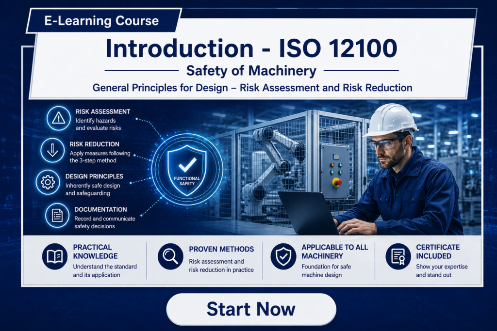
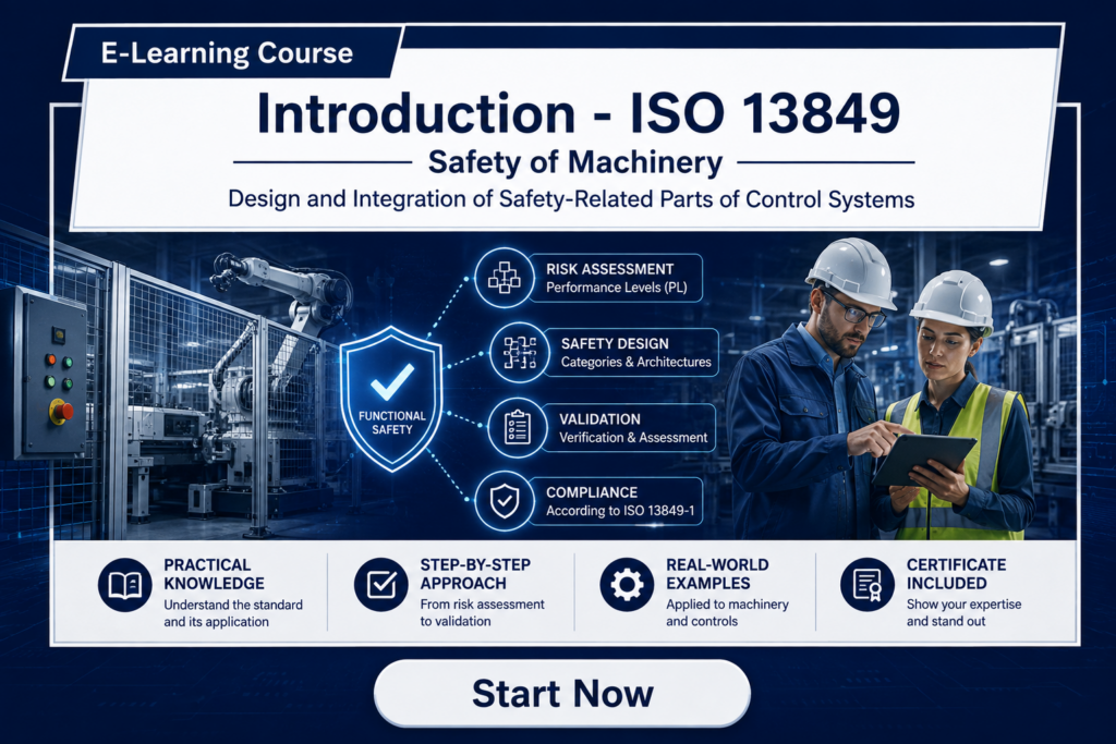
Our professional ISO 13849 online training explains how safety functions, Performance Levels, architectural categories, reliability parameters and verification fit together in machinery Functional Safety.
The course provides a structured introduction to the standard with practical engineering explanations and examples.
Practical Example – From Hazard to Performance Level
Consider a machine with hazardous moving components that are accessible through a movable safety guard.
During normal production, the guard remains closed. However, an operator may need to open the guard to access the machine.
The safety engineering process should not begin by simply selecting a safety relay or safety controller.
It begins with the hazard.
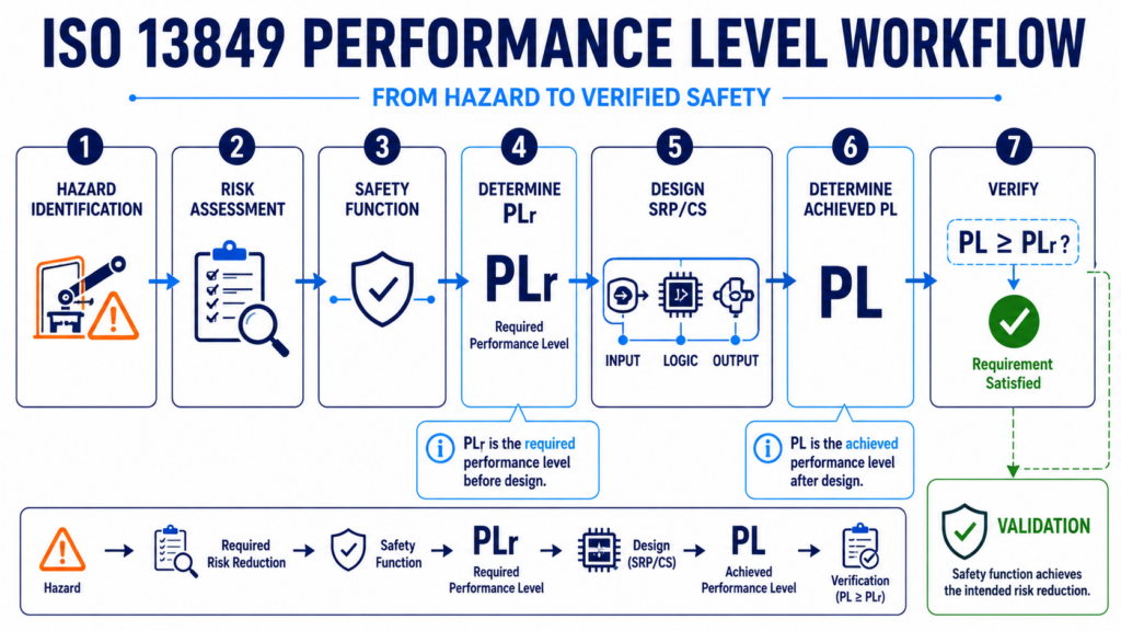
Step 1 – Identify the Hazard
Hazardous machine movement could result in injury if a person enters the hazardous area while the machine remains active.
The hazard and corresponding hazardous situations are identified as part of the machinery risk assessment.
Step 2 – Define the Safety Function
A safety function is defined to reduce the identified risk.
In simplified form:
Opening the safety guard shall initiate a safe stop of the hazardous machine movement.
The safety function now provides a clear connection between the identified hazard and the safety-related control system.
Step 3 – Determine the Required Performance Level
The severity of potential injury, frequency or duration of exposure and possibility of avoiding the hazard are evaluated.
The risk graph is then used to determine the required Performance Level.
For illustration, assume the assessment results in:
PLr = d
The safety function must therefore be implemented so that the achieved Performance Level satisfies this requirement.
Step 4 – Design the Safety-Related Control System
The safety function could involve several elements:
Guard switch → Safety controller → Output stage → Actuator
The architecture must be designed with the required Performance Level in mind.
Component reliability, diagnostic measures, fault behavior and potential common cause failures are evaluated as part of the design.
Step 5 – Verify the Achieved Performance Level
Once the architecture and component parameters are known, the achieved Performance Level can be evaluated.
Suppose the resulting design achieves:
PL = d
Since:
Achieved PL d ≥ Required PLr d
the Performance Level requirement is satisfied.
However, this verification alone does not replace validation of the complete safety function.
How SISTEMA Supports Performance Level Evaluation
For practical ISO 13849 projects, calculations and architecture evaluations can quickly become complex.
The SISTEMA software tool supports engineers in evaluating safety-related control systems according to ISO 13849.
A safety function can be represented using its safety-related subsystems and components. Relevant reliability and diagnostic parameters can then be entered and evaluated.
Typical information considered includes:
- Component reliability data
- MTTFd
- Diagnostic Coverage
- Common Cause Failure measures
- Architecture
- PFHd
SISTEMA can therefore support the quantitative evaluation of whether a designed safety function achieves the required Performance Level.
However, the tool does not replace the underlying safety engineering process.
Engineers still need to correctly define safety functions, determine the required Performance Level, select appropriate architectures, use valid component data and validate the implemented safety function.
Future internal link: Mark “SISTEMA” → dedicated SISTEMA article once published.
Performance Level Verification and Validation
Verification and validation are essential parts of the ISO 13849 workflow.
Although the terms are closely related, they answer different questions.
Performance Level Verification
Verification examines whether the designed safety-related control system satisfies the specified requirements.
One important question is:
Does the achieved Performance Level meet or exceed PLr?
The architecture and relevant parameters are evaluated to provide evidence that the required level has been achieved.
Safety Function Validation
Validation takes a broader view.
The objective is to demonstrate that the implemented safety-related parts of the control system actually perform the intended safety function under the relevant conditions.
This includes more than comparing two Performance Level values.
For the safety-guard example, validation must consider whether opening the guard actually produces the intended safe response and whether the complete safety function behaves correctly under foreseeable conditions.
Verification and validation therefore provide complementary evidence that the safety-related control system has been appropriately designed and implemented.
How ISO 12100 and ISO 13849 Work Together
ISO 12100 and ISO 13849 address different but closely connected aspects of machinery safety.
ISO 12100 establishes fundamental principles for risk assessment and risk reduction.
A simplified ISO 12100 process is:
Hazard Identification → Risk Estimation → Risk Evaluation → Risk Reduction
Where risk reduction depends on a safety-related control function, ISO 13849 can then provide a framework for designing and evaluating the safety-related parts of the control system.
The resulting relationship can be understood as:
Hazard
↓
Risk Assessment
↓
Required Risk Reduction
↓
Safety Function
↓
Required Performance Level (PLr)
↓
Safety-Related Control System
↓
Achieved Performance Level (PL)
↓
Verification & Validation
The standards should therefore not be viewed as isolated approaches.
ISO 12100 provides the broader machinery risk-reduction framework, while ISO 13849 addresses the safety-related control-system aspects where appropriate.
ISO 13849 and IEC 62061
ISO 13849 is not the only standard relevant to Functional Safety of machinery control systems.
IEC 62061 also addresses the functional safety of safety-related control systems for machinery.
While ISO 13849 uses concepts such as Performance Levels and Categories, IEC 62061 follows an approach based on concepts including Safety Integrity Levels.
The standards therefore use different methodologies, even though they address closely related machinery Functional Safety challenges.
Selecting and applying the appropriate framework requires an understanding of the machine, the safety functions and the applicable project context.
A dedicated comparison of ISO 13849 vs IEC 62061 will explore these differences in more detail.
ISO 13849 Performance Levels – Key Takeaways
Performance Levels provide a structured approach for specifying and evaluating the risk-reduction capability of safety-related parts of machinery control systems.
The most important points are:
- ISO 13849 defines Performance Levels from PL a to PL e.
- PLr represents the required Performance Level of a safety function.
- The required Performance Level originates from risk-related considerations.
- The achieved PL depends on architecture, reliability, diagnostics and additional measures.
- The achieved Performance Level must satisfy the required PLr.
- SISTEMA can support quantitative Performance Level evaluation.
- Verification and validation complete the safety-related development process.
- ISO 12100 and ISO 13849 form closely connected parts of machinery risk reduction.
The key principle is simple:
Do not start with a component or architecture and ask how safe it is. Start with the hazard, determine the necessary risk reduction, define the safety function and then design a solution capable of achieving the required Performance Level.
Learn More About Machinery Functional Safety
Understanding Performance Levels is only one part of applying Functional Safety principles to machinery.
Our professional online training portfolio provides structured introductions to machinery safety standards and explains how risk assessment, safety functions, safety-related control systems and verification connect in engineering practice.
Explore our professional engineering online training courses →