ISO 13849 Categories Explained – Categories B, 1, 2, 3 and 4
ISO 13849 uses different architectural Categories to describe important characteristics of safety-related parts of control systems, commonly referred to as SRP/CS.
The Categories range from Category B to Categories 1, 2, 3 and 4. They define requirements related to the architecture of the safety-related control system, the use of safety principles, fault detection and the behavior of the system when faults occur.
However, an important distinction is often misunderstood:
The Category of a safety-related control system is not the same as its Performance Level.
The Category is one of several factors that influence the achieved Performance Level. Reliability, diagnostic coverage, common cause failures and systematic aspects must also be considered.
This article explains the five ISO 13849 Categories, their fundamental differences and how they contribute to the evaluation of the achieved Performance Level.
What Are Categories in ISO 13849?
Categories provide a classification of the architecture and fault behavior of safety-related parts of control systems.
They help describe how a safety function is implemented and, in particular, how the control system responds when faults occur.
Depending on the Category, the design may rely primarily on suitable components and safety principles, periodically test the safety function, or use redundant channels combined with diagnostic measures.
The five Categories are:
- Category B
- Category 1
- Category 2
- Category 3
- Category 4
Moving from Category B toward Category 4 generally introduces increasingly demanding requirements concerning fault tolerance and fault detection.
However, the Categories should not simply be interpreted as five sequential “safety levels.” Their architectures and requirements differ in important ways.
Overview of ISO 13849 Categories B, 1, 2, 3 and 4
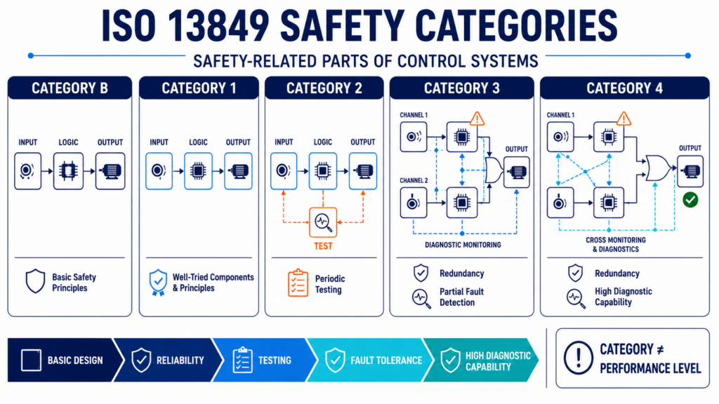
The fundamental characteristics can be summarized as follows:
| Category | Basic Concept | Fault Detection | Redundancy |
|---|---|---|---|
| B | Basic safety principles | Not generally required | Not required |
| 1 | Well-tried components and safety principles | Not generally required | Not required |
| 2 | Periodic testing of the safety function | Testing required | Not necessarily redundant |
| 3 | Redundant architecture with diagnostics | Partial fault detection | Typically redundant |
| 4 | High fault tolerance and diagnostic capability | High fault detection | Redundant |
This overview is useful for understanding the general progression, but the Category alone does not determine the achieved Performance Level.
For example, selecting a Category 3 architecture does not automatically mean that the safety function achieves PL d.
Category B – Basic Safety Principles
Category B represents the fundamental basis for the design of safety-related parts of control systems.
The components must be selected, assembled and applied according to relevant standards and basic safety principles so that they are suitable for the intended application and expected environmental conditions.
Examples of considerations include:
- expected mechanical and electrical stresses
- environmental influences
- component suitability
- appropriate design principles
- foreseeable operating conditions
Category B does not generally rely on redundancy or dedicated diagnostic measures to maintain the safety function after a fault.
A fault can therefore lead to the loss of the safety function.
The emphasis is primarily on appropriate design and the application of basic safety principles.
Category 1 – Well-Tried Components and Safety Principles
Category 1 builds on the principles of Category B but introduces additional requirements.
Safety-related parts must use well-tried components and well-tried safety principles where applicable.
The objective is to reduce the probability that dangerous faults occur in the first place.
A simplified conceptual architecture may still consist of a single functional channel:
Input → Logic → Output
There is not necessarily a redundant second channel or continuous diagnostic system.
Consequently, a single fault can still result in the loss of the safety function.
The improvement compared with Category B therefore comes primarily from increased reliability through suitable components and established safety principles rather than increased fault tolerance.
Category 2 – Testing of the Safety Function
Category 2 introduces an important new concept:
The safety function is tested at suitable intervals.
In addition to the functional channel, the architecture includes measures that test the safety-related system.
A simplified representation could be:
Input → Logic → Output
combined with:
Test Equipment → Functional Channel
The purpose of the test is to identify faults that could impair the safety function.
If a dangerous fault is detected, an appropriate response must follow.
This creates an important distinction from Categories B and 1. The system no longer relies exclusively on preventing failures through appropriate design and component selection. It also introduces active fault detection through testing.
However, testing is not necessarily continuous.
A dangerous fault can therefore occur between two tests and may affect the safety function until the next test detects it.
The relationship between the test frequency, demand on the safety function and overall architecture therefore becomes important.
Category 3 – Redundancy and Partial Fault Detection
Category 3 introduces a fundamentally different architectural concept.
The safety-related system is designed so that a single fault does not lead to the loss of the safety function.
This commonly requires a redundant architecture.
A simplified example is:
Input Channel 1 → Logic Channel 1 → Output Channel 1
Input Channel 2 → Logic Channel 2 → Output Channel 2
Diagnostic or monitoring mechanisms can compare or supervise relevant parts of these channels.
If one component fails, the remaining architecture should still allow the safety function to be performed.
This represents an important increase in fault tolerance compared with Categories B, 1 and 2.
However, Category 3 does not require every possible fault to be detected.
Some faults may therefore remain undetected.
If multiple undetected faults accumulate, the safety function can eventually be lost.
This issue of fault accumulation becomes one of the important distinctions between Categories 3 and 4.
Category 4 – High Fault Tolerance and Diagnostic Capability
Category 4 represents the most demanding architectural Category within the ISO 13849 Category concept.
As with Category 3, a single fault must not lead to the loss of the safety function.
However, Category 4 places stronger requirements on fault detection and the handling of accumulated faults.
The architecture commonly combines:
Redundancy
with
High Diagnostic Capability
and
Measures Against Fault Accumulation
Where practicable, faults must be detected at or before the next demand upon the safety function. Where this is not possible, an accumulation of undetected faults must not lead to the loss of the safety function.
This results in a high level of resistance to dangerous failures.
Category 4 architectures are therefore typically associated with safety functions requiring very high risk reduction capability.
However, even Category 4 does not automatically guarantee PL e.
The complete Performance Level evaluation is still necessary.
Category vs Performance Level – What Is the Difference?
This is one of the most important concepts when working with ISO 13849.
A Category describes architectural and fault-behavior characteristics of the safety-related control system.
A Performance Level describes the capability of the safety-related parts of the control system to perform the safety function under foreseeable conditions.
The achieved Performance Level is classified from:
PL a → PL b → PL c → PL d → PL e
with increasing capability for risk reduction.
Therefore:
Category ≠ Performance Level
Instead, the Category is one important input into the determination of the achieved Performance Level.
Want to Learn ISO 13849 in More Detail?
Our professional ISO 13849 online training explains how safety functions, Performance Levels, architectural categories, reliability parameters and verification fit together in machinery Functional Safety.
The course provides a structured introduction to the standard with practical engineering explanations and examples.
How Category Influences the Achieved Performance Level
The achieved Performance Level cannot be determined from the Category alone.
Several parameters must be considered together.
A useful conceptual relationship is:
Category + MTTFd + DCavg + CCF + Systematic Measures → Achieved PL
Each element addresses a different aspect of the safety-related control system.
Category
The Category establishes important requirements for the system architecture and its behavior under fault conditions.
It determines, for example, whether redundancy or testing is required and how the system must behave when faults occur.
MTTFd – Mean Time to Dangerous Failure
MTTFd describes the expected reliability of components or channels with respect to dangerous failures.
Higher component reliability reduces the probability that dangerous failures occur.
MTTFd therefore complements the architectural characteristics represented by the Category.
DCavg – Average Diagnostic Coverage
Diagnostic Coverage describes the effectiveness of diagnostic measures in detecting dangerous failures.
This becomes particularly important for architectures that rely on diagnostics to identify faults.
CCF – Common Cause Failures
Redundancy alone does not guarantee independence.
A single common cause can potentially affect multiple channels simultaneously.
Examples can include:
- common power supply failures
- environmental influences
- electromagnetic disturbances
- systematic design weaknesses
- insufficient physical separation
Measures against Common Cause Failures are therefore particularly important in redundant architectures.
Which Categories Can Achieve Which Performance Levels?
It is tempting to create a simple one-to-one relationship such as:
Category 3 = PL d
or
Category 4 = PL e
But this interpretation is incorrect.
The achievable Performance Level depends on the combination of Category, component reliability, diagnostic coverage and other relevant requirements.
The Category provides the architectural foundation, while the remaining parameters determine whether the complete implementation achieves the required level of performance.
This is why two safety functions using broadly similar architectures can still achieve different Performance Levels.
The complete design must always be evaluated rather than assigning a Performance Level based only on the Category name.
Practical Example – Emergency Stop Safety Function
Consider a machine with a rotating drive that can create a hazardous situation for an operator.
A risk assessment identifies the need for an emergency stop function.
The required safety function could be described conceptually as:
Emergency Stop Activated → Machine Motion Safely Stopped
The required Performance Level, PLr, is determined based on the risk associated with the hazardous situation.
The safety-related control system must then be designed to provide the required risk reduction.
Single-Channel Concept
A simple architecture could consist of:
Emergency Stop → Control Element → Contactor → Motor
If a dangerous failure occurs in a critical component, the safety function could potentially be lost.
Simply having an emergency stop button therefore does not tell us the Performance Level of the complete safety function.
Redundant Concept
A more fault-tolerant architecture could use redundant channels:
Emergency Stop Contacts
↓
Safety Relay / Safety Controller
↓
Two Switching Elements
↓
Machine Drive
Monitoring can be used to detect relevant faults in the switching elements or other parts of the safety-related control system.
The architecture can therefore tolerate certain individual faults without immediately losing the safety function.
However, the achieved Performance Level still depends on the complete quantitative and qualitative evaluation.
Category 3 vs Category 4 – What Is the Difference?
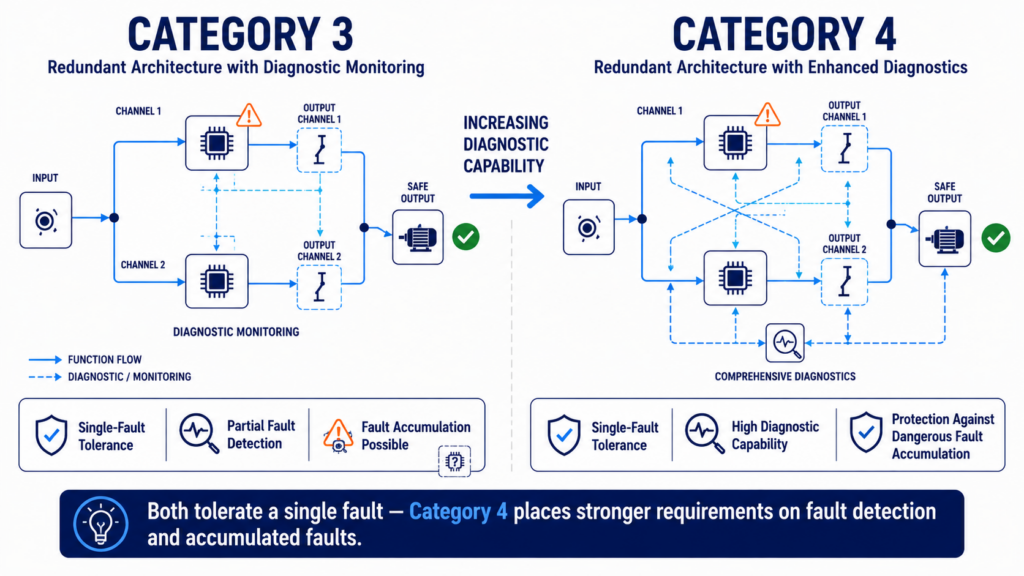
Categories 3 and 4 are frequently confused because both typically use redundant structures and require that a single fault does not lead to the loss of the safety function.
The key difference lies particularly in the extent of fault detection and the treatment of accumulated faults.
In Category 3, not every fault necessarily has to be detected. Undetected faults can therefore accumulate and, under certain circumstances, eventually lead to the loss of the safety function.
Category 4 requires stronger diagnostic behavior and fault tolerance. Faults should be detected sufficiently early, and the architecture must address the possibility of fault accumulation so that the safety function is not lost.
A useful conceptual distinction is therefore:
Category 3 → Single-fault tolerance + diagnostic measures
Category 4 → Single-fault tolerance + high diagnostic capability + stronger protection against fault accumulation
The actual assessment must nevertheless consider the complete implementation rather than only this simplified distinction.
How SISTEMA Supports Category Evaluation
For practical ISO 13849 engineering, calculations and architecture evaluation can become complex.
The SISTEMA software developed by the German Institute for Occupational Safety and Health supports engineers in evaluating safety-related control systems according to ISO 13849-1.
A safety function can be represented using subsystems and relevant reliability parameters.
The engineer can then model characteristics such as:
- architecture
- MTTFd
- Diagnostic Coverage
- Common Cause Failure measures
- resulting Performance Level
SISTEMA therefore provides a structured way to support the Performance Level evaluation.
However, the software does not replace the engineering process itself.
The safety function, required Performance Level, architecture, components and assumptions must still be defined correctly.
Verification of the Selected Architecture
After designing the safety-related parts of the control system, the achieved Performance Level must be verified against the required Performance Level.
The fundamental relationship is:
Achieved PL ≥ Required PLr
If the achieved Performance Level does not meet the required PLr, the safety-related control system does not provide the required risk reduction.
Possible design improvements may include:
- improving the architecture
- selecting more reliable components
- improving diagnostic measures
- reducing susceptibility to common cause failures
- modifying the safety-related design
Verification therefore closes the loop between the original risk assessment and the implemented safety function.
How ISO 12100 and ISO 13849 Work Together
ISO 12100 and ISO 13849 address different but closely connected parts of machinery safety engineering.
ISO 12100 provides fundamental principles for machinery risk assessment and risk reduction.
The process begins by identifying hazards, estimating and evaluating risks, and determining appropriate risk reduction measures.
When a risk reduction measure depends on a safety-related control function, ISO 13849 can be used to design and evaluate the corresponding safety-related parts of the control system.
A simplified relationship is:
Hazard
↓
Risk Assessment
↓
Risk Reduction
↓
Safety Function
↓
Required Performance Level (PLr)
↓
SRP/CS Architecture
↓
Achieved Performance Level
The Categories therefore form one important part of a much larger machinery Functional Safety process.
ISO 13849 Categories and IEC 62061
ISO 13849 is not the only standard used for the Functional Safety of machinery control systems.
IEC 62061 provides another framework for the design of safety-related control systems for machinery.
While ISO 13849 uses the Performance Level concept and Categories B, 1, 2, 3 and 4, IEC 62061 uses a Safety Integrity Level based approach.
Both standards ultimately support the engineering of safety-related control functions, but their methods, terminology and evaluation concepts differ.
Understanding both approaches is particularly useful for engineers working across different machinery projects and organizations.
Key Takeaways
The Categories in ISO 13849 describe important architectural and fault-behavior characteristics of safety-related parts of control systems.
Category B establishes basic design and safety principles.
Category 1 additionally relies on well-tried components and well-tried safety principles.
Category 2 introduces testing of the safety function.
Category 3 introduces fault tolerance through redundant architecture combined with diagnostic measures.
Category 4 provides the most demanding architectural requirements, with high diagnostic capability and stronger protection against dangerous fault accumulation.
However, the most important point is:
Category does not equal Performance Level.
The achieved Performance Level depends on the complete safety-related design, including architecture, MTTFd, Diagnostic Coverage, Common Cause Failures and other relevant requirements.
The selected architecture must ultimately support an achieved Performance Level that satisfies the required Performance Level:
PL ≥ PLr
Learn More About Machinery Functional Safety
Understanding Categories is only one part of designing safety-related control systems according to ISO 13849.
Engineers must also understand how machinery risks are evaluated, how safety functions are specified, how the required Performance Level is determined and how the final architecture is verified.
Our professional online training portfolio provides structured introductions to machinery safety standards and explains how these engineering activities connect in practice.
Explore our professional Machinery Functional Safety online training courses →